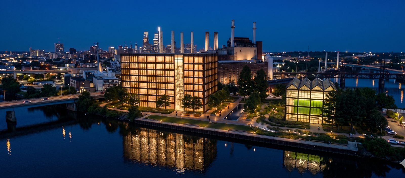
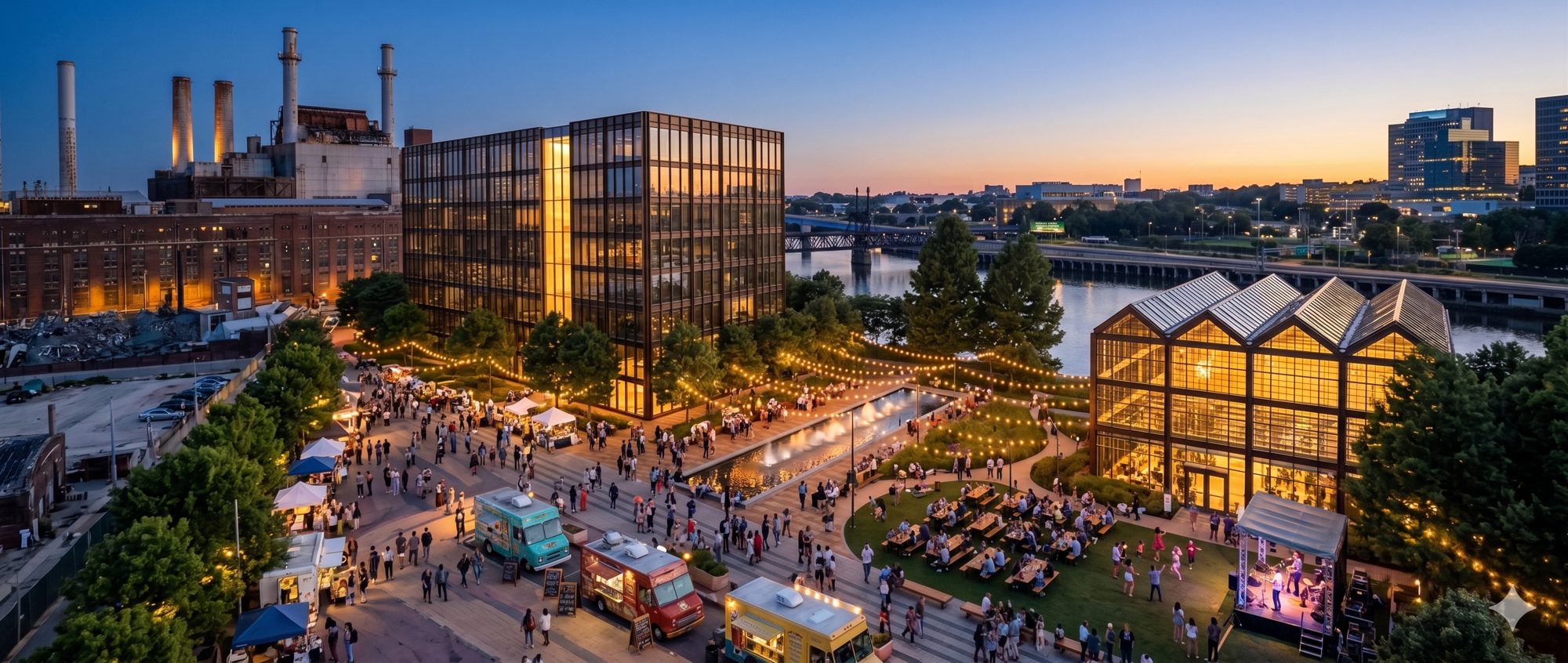
01
Scroll or use arrow keys
MICROLINK® DATA CENTERS

Philadelphia

The River Site

A liquid-cooled data center built with its host,
returning its heat to the city.

The River Site at dusk, on the river with the plant and bridge behind
Partners  Nvidia · Vertiv · Vicinity Offtake  80 MW confirmed For  City, community, host and technology partners
Working draft · for partner and stakeholder discussion
At a GlanceThe River Site · Philadelphia 80 MW

The numbers that matter.

Data center IT load80 MW
Heat delivered to the district system20 to 22 MW thermal
Recoverable heat at the data center68 MW thermal
CO₂ avoided for the host36,000 t/yr
Land we need1.5 to 2 ha (3.7 to 4.9 acres)
Behind-the-meter power from the host plantup to 20 MW
New front-of-meter interconnection60 to 80 MW (PECO 230 kV, PJM)
Natural gas displaced for the host660,000 Mcf/yr
Host gas cost avoided$3.2M to $7.2M/yr
Loop temperature delivered40 to 65°C (104 to 149°F)
Heat source availability24/7 constant
Pilot tie-in size6 MW thermal
Future heat-pump source duty23 MW to a 35 MW class unit
Heat-pump electricity saved (future)18 to 29% per unit steam
Tie-in pointPlate HX on the RO makeup line
PUE1.10 to 1.15
EREbelow 1.0 over delivered heat
Heat reuse fraction (ERF)30% interim, rising
Process water for coolingzero
Total facility electrical load88 to 92 MW
Electrical service / intake100 MVA
Load factor90% or higher
Behind-the-meter power cost targetbelow $90/MWh
CO₂ in cars-equivalent7,800 cars off the road
Reliability guaranteeDry coolers sized for full load
Cost to the host’s ratepayersnone
Commercial structurePartner terms, no revenue share
Capital invested by MicroLink$1.05B at 80 MW
Construction jobs500 to 900 at peak
Permanent jobs275 at 80 MW
Part One

The Presentation

The case, and the options on the table for
everyone in the room.

01 / The ProblemPart One

Power is the bottleneck.
The heat is wasted.

  • AI compute is constrained by power, not by chips or capital. New large loads wait years to connect to the grid.
  • PJM capacity prices stepped from $28.92 to $329.17 per MW-day across two auction cycles, close to an eleven times rise.
  • Meanwhile close to 100% of the power a data center draws leaves as low-grade heat that is thrown away.
Chart
PJM interconnection queue and capacity-price step
02 / The InsightPart One
Diagram
Greenfield versus host co-location, time to power

Build with a host.

  • Site at an industrial host that already holds power and grid allocation and has a use for the heat.
  • The host has the interconnection a greenfield project waits years for, and a heat sink already in the ground. Two problems solved at once.
  • Hosts are partners, never customers. We advance the partner's own strategy on the partner's terms.
03 / The OfftakerPart One

The 80 MW is
spoken for.

  • The full 80 MW has a confirmed offtaker on a long-term basis.
  • Demand is not the open question on this deal. The work is power, site, and delivery.

[Offtaker disclosure to confirm: named, described generically, or held back.]

Image
Offtaker lockup or logo, pending disclosure decision
04 / The SitesPart One

Three candidate sites.
One we build first.

We are pitching three candidate parcels. The River Site is our recommended anchor for 80 MW and the one we deep-dive next. None is locked; siting follows the power study.
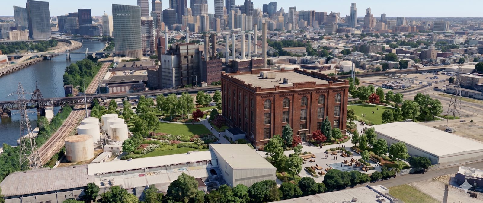
The River Site, the anchor parcel
Secondary candidate site
05 / The ModelPart One

Heat, power, lease.

The differentiator

Heat recovery

Liquid cooling recovers heat at 40°C to 65°C (104°F to 149°F) and delivers it into useful systems.

Lead with this
The primary offer

Behind-the-meter power

Power secured below grid retail by sitting behind the meter and avoiding transmission, distribution, and capacity charges.

The commercial engine
The third stream

Long-term lease

A long-term facility lease anchors the deployment on the partner's balance-sheet terms. No revenue share.

The anchor
06 / The MetricPart One

ERE below 1.0, reported
with PUE.

PUE measures how efficiently we consume. ERE measures the net, after the heat we return. We report them together, always.

1.10 to 1.15
PUE target
Liquid cooling, no mechanical refrigeration
<1.0
ERE, host taking heat
More useful energy leaves than overhead consumes
Low
WUE
Dry-cooler reject path uses no process water

ERE counts only heat delivered across the host boundary. With no offtake, ERE equals PUE.

07 / The PartnersPart One

The stack.

Compute

Nvidia

The NVIDIA Cloud Partner reference architecture, GB200 NVL72 and NVL144 class.

Cooling and power

Vertiv

Direct-to-chip liquid cooling and the CDU at the boundary.

Host energy partner

Vicinity

District energy, and the heat host for the recovered warm loop.

Image
Partner logo lockup
Part Two

The River Site

The property, and how we propose to build it.

08 / The River SitePart Two
The park between the data center and the public center

Why the river parcel.

  • River frontage, power on or beside the parcel, a heat sink next door.
  • Room for a three-building campus, and the clearest reference for the design options.

[Parcel specifics to confirm: area, control, power and heat-sink distances.]
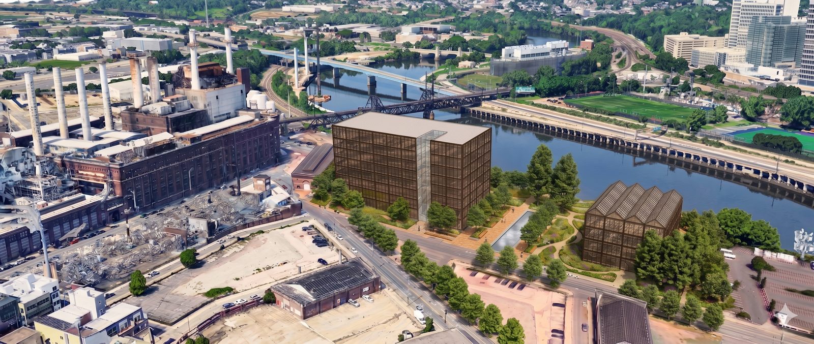
09 / The CampusPart Two

Three buildings.

A data center, a plant, and a public center with a greenhouse. Heat runs from the data center, through the plant, to the public center.
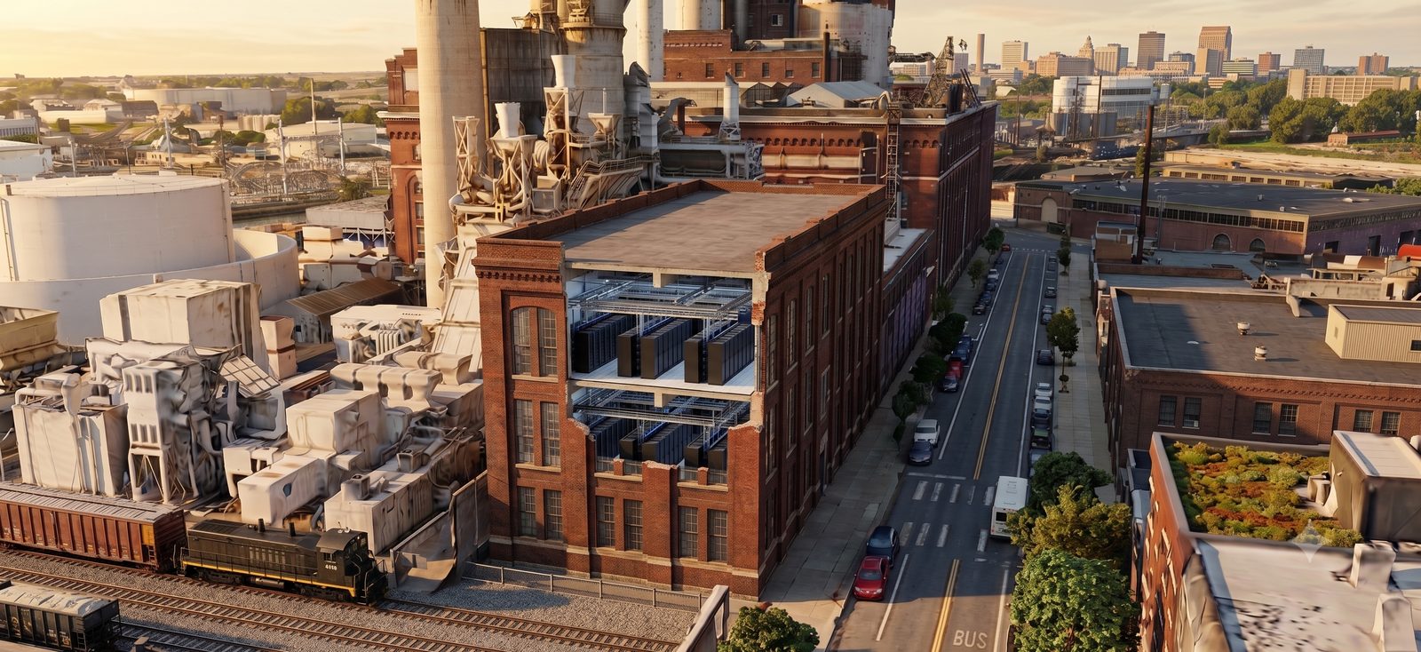
Diagram
Campus flow: Data Center to Plant to Public Center and Greenhouse
Site plan and massing on the river parcel
10 / Building OnePart Two
The data center, brick facade and glazed atrium pipe gallery

The Data Center.

  • 80 MW. Five storey, ground plus four data floors of 20 MW each.
  • Direct-to-chip liquid cooling, CDUs at the boundary, cores and risers stacked.
  • Behind-the-meter power in. Tier III, concurrently maintainable, N+1.
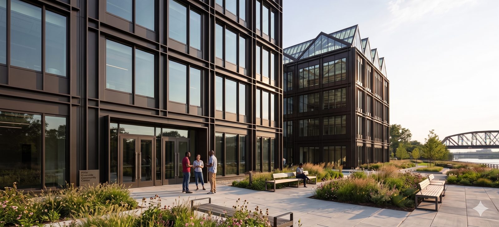
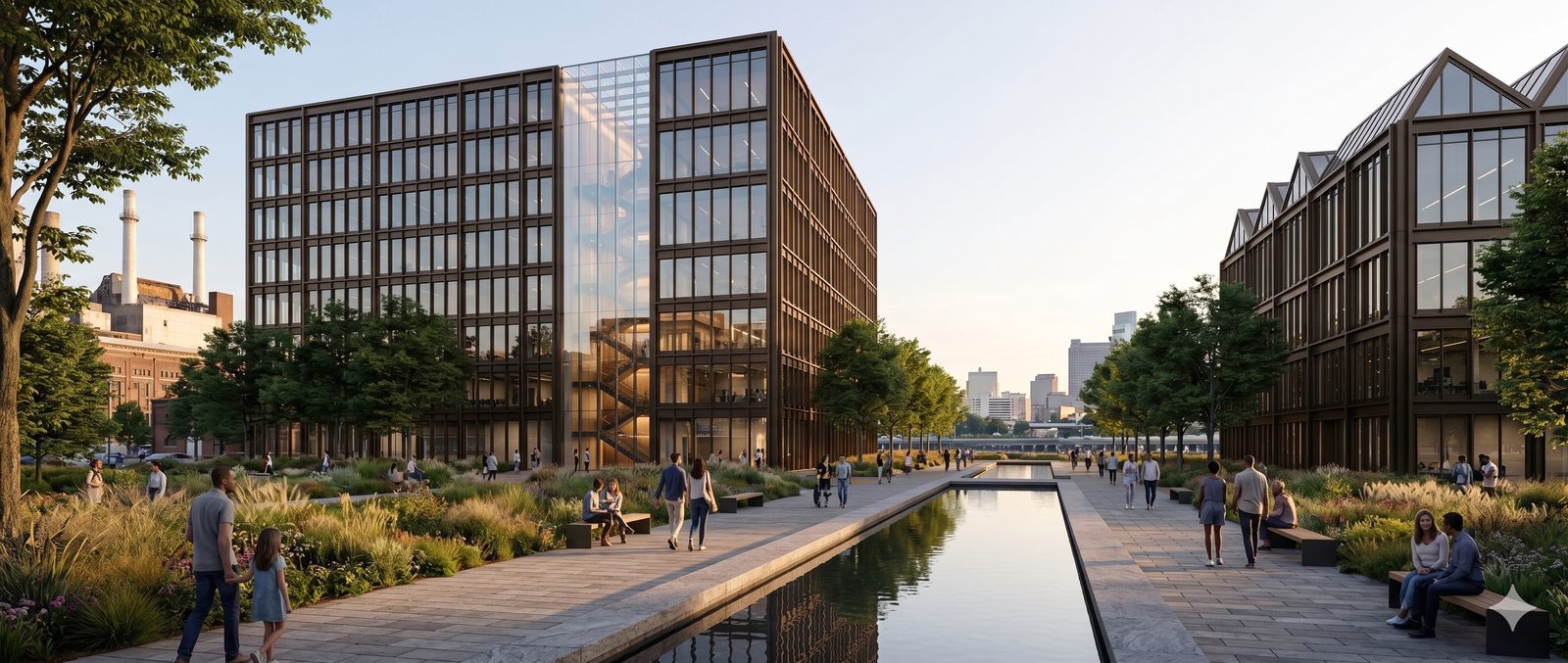
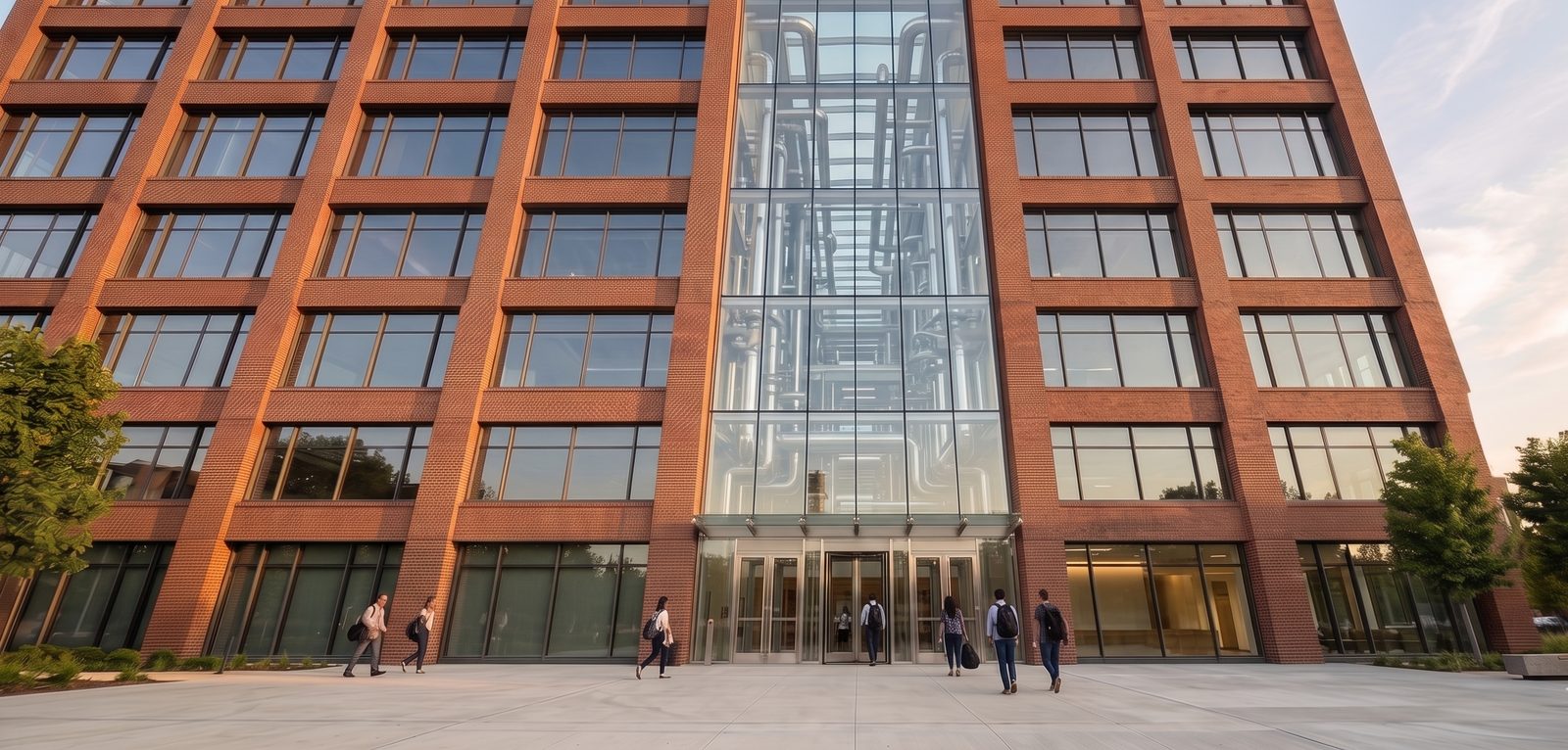
11 / Building TwoPart Two

The Plant.

  • The hinge between the data center and the public center, on its own work stream.
  • Heat recovery exchangers keep the data center fluid fully separate from the host circuit.
  • The dry-cooler reject path is always present and sized for the full load, so IT cooling never depends on heat offtake.
Render
Plant building, mechanical, dry coolers visible
12 / Building ThreePart Two
The Public Center, greenhouse roof and forecourt

The Public Center.

  • Two storey. Community, office, and a craft brewery, with a greenhouse and a public forecourt.
  • It receives recovered hot water from the plant.
  • Built here, in the design. Programmed in Part Three, the community track.
13 / PowerPart Two

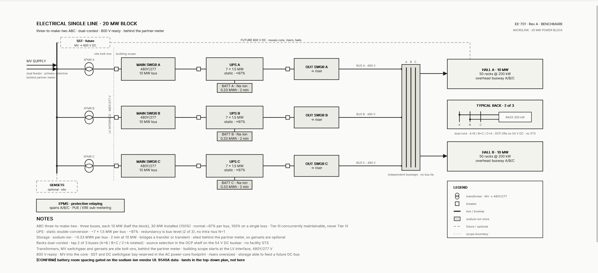
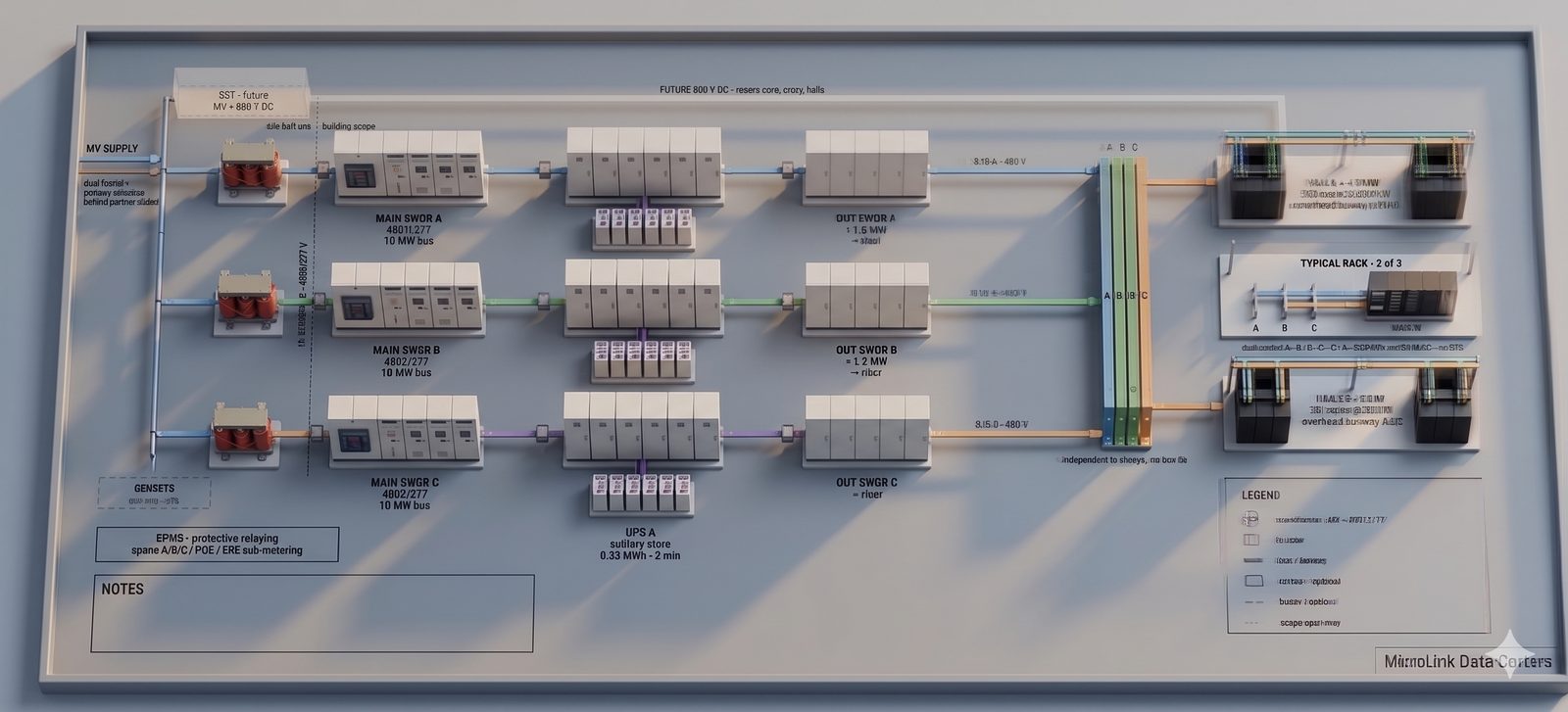
Power, built three to make two.

Three buses, sized so any two carry the full load. Dual-corded, 800 V ready, and behind the partner meter.

  • A 3M2 distributed redundant topology, Tier III and concurrently maintainable, so any one path can drop for service without touching the load.
  • Total facility electrical load of 88 to 92 MW on a 100 MVA service, with a behind-the-meter power cost target below $90/MWh.
  • Up to 20 MW drawn behind the partner meter, the balance on a new 60 to 80 MW front-of-meter interconnection at PECO 230 kV into PJM.
Power single line
Single line · EE-701
Power isometric
Isometric
14 / Cooling DistributionPart Two

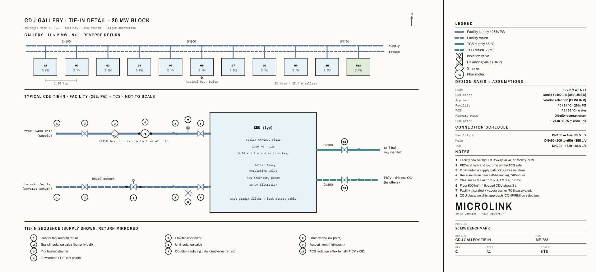
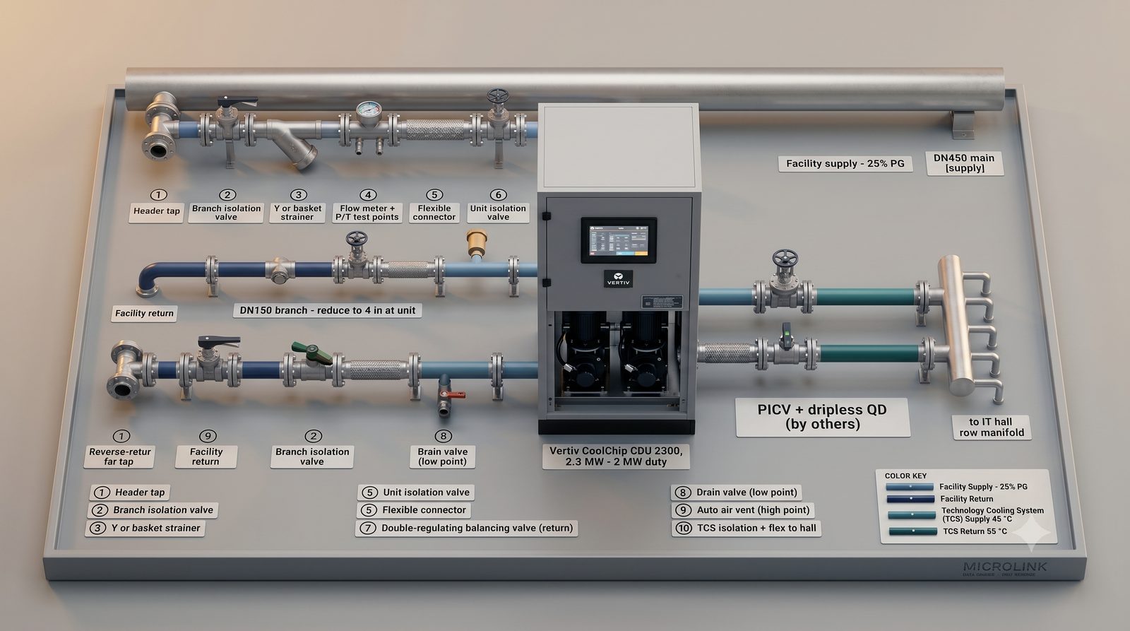
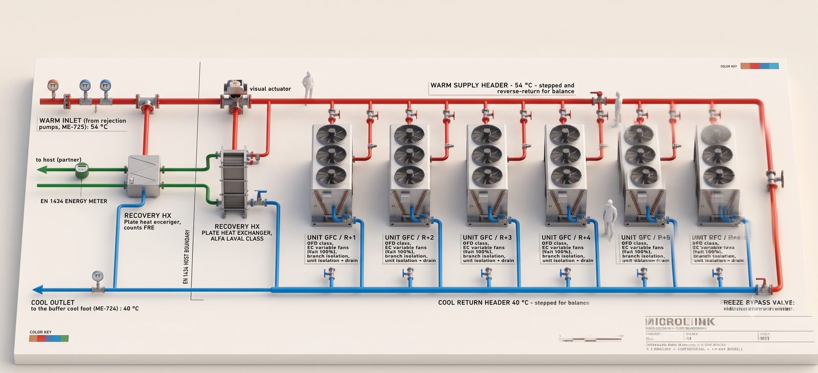
Where the loops meet.

The CDU gallery is the boundary between the chip loop and the facility loop. Eleven units at N+1, on a reverse return for balance.

  • Direct-to-chip liquid cooling, with the CDU sitting at the boundary so the chip loop and the facility loop never mix.
  • DN450 reverse-return headers carry about 355 L/s at a 14 K delta-T on a 25% propylene glycol facility loop, balanced by design.
  • No mechanical refrigeration, so the hall runs at a PUE of 1.10 to 1.15 with ERE below 1.0 once the partner takes the heat.
Cooling Distribution single line
Tie-in detail · ME-723
Cooling Distribution isometric
Isometric · Vertiv CoolChip CDU
15 / Cooling and Heat RecoveryPart Two

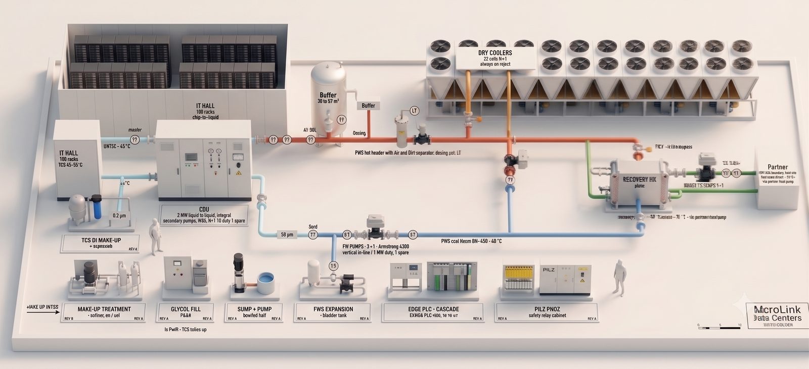
Three loops, one boundary.

Chip, facility, and recovery loops meet at the CDU, so no central separation heat exchanger is needed.

  • Recovered heat leaves at 40 to 65 °C (104 to 149 °F), metered across the host boundary before it reaches the partner.
  • The dry-cooler reject path sits on the always-open leg, sized for the full load, so IT cooling never depends on heat offtake.
  • 20 to 22 MW thermal returned to the district system, displacing about 660,000 Mcf/yr of gas for the host.
Cooling and Heat Recovery single line
P&ID · ME-702
Cooling and Heat Recovery isometric
Isometric
16 / The Heat Recovery GalleryPart Two

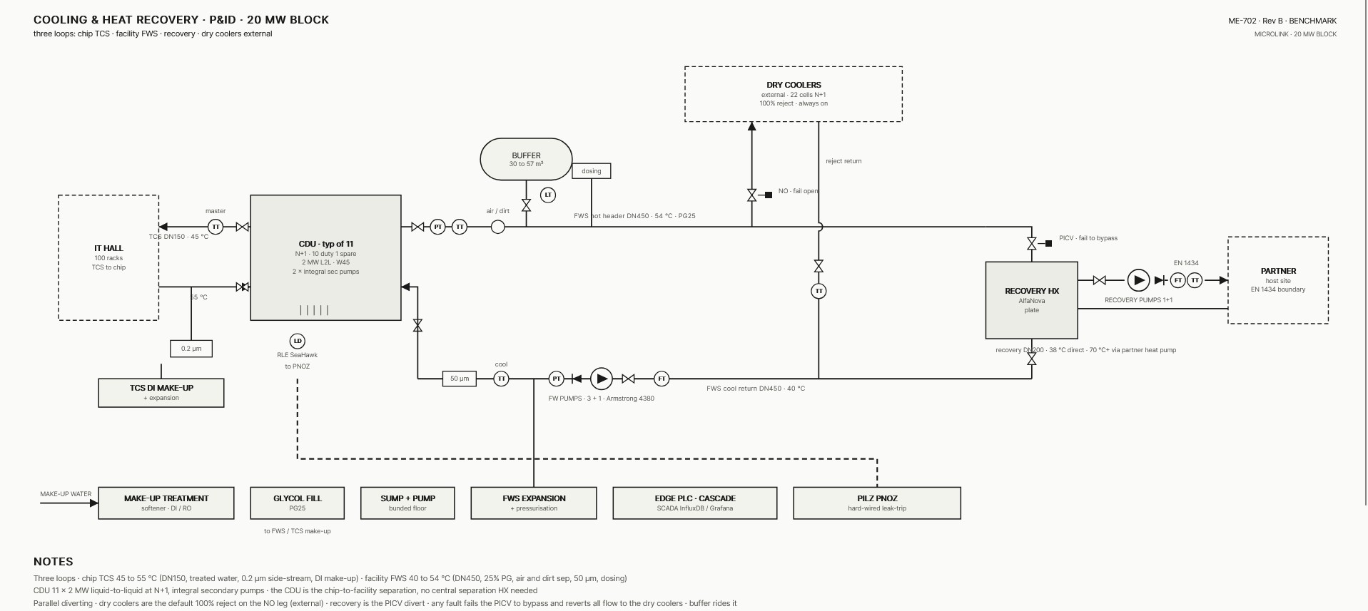
Where the heat is measured.

Warm water off the rejection pumps passes a recovery heat exchanger metered to EN 1434, the point where recovered heat is counted before it reaches the partner. The dry coolers take the balance, so rejection is always available.
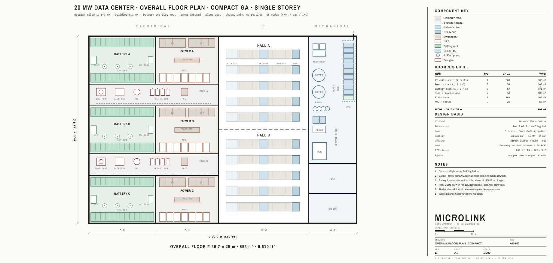
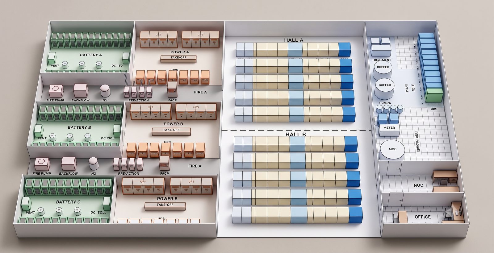
Heat recovery gallery isometric
Isometric · warm supply header, recovery heat exchanger, and dry coolers
17 / The Floor PlanPart Two

20 MW on one floor.

A single storey of 893 m² (9,610 ft²). Two halls in the centre, power and battery to the west, plant to the east, with the dry coolers carried outside.

  • Ground plus four identical 20 MW floors stack to the full 80 MW, so the block grows by storey rather than by redesign.
  • Cores and risers stacked, CDUs at the boundary of each hall, dual-corded down to the floor distribution.
  • The dry coolers are carried outside the envelope, keeping the reject path independent of the occupied floor.
The Floor Plan single line
General arrangement · AE-100
The Floor Plan isometric
Isometric
18 / DeploymentPart Two

How it gets built.

80 MW built directly as four 20 MW data floors. A 20 MW opening phase remains optional. The power path is gated on the studies and confirmed land.

Gate 01
Site and power
PECO load study, PJM deliverability, confirmed land
Gate 02
Design and permitting
Basis of design, general arrangement, entitlements
Gate 03
Build
Construction with Philadelphia trades
Gate 04
Commercial operation
Energized, handed to the offtaker
Part Three

The Community

Separate from the build.
Themed on energy and heat recovery.

The data center stands on its own. The community work is its own commitment, connected only by the hot water that leaves the plant.
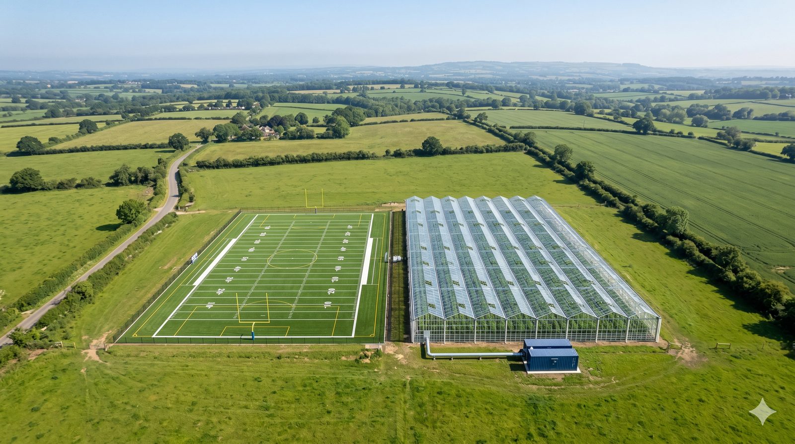
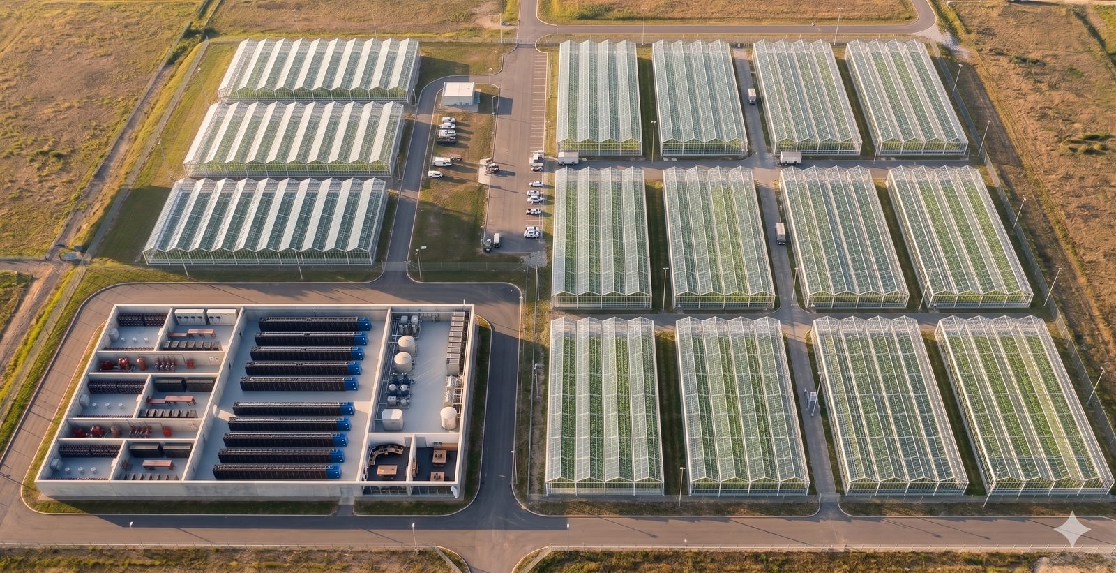
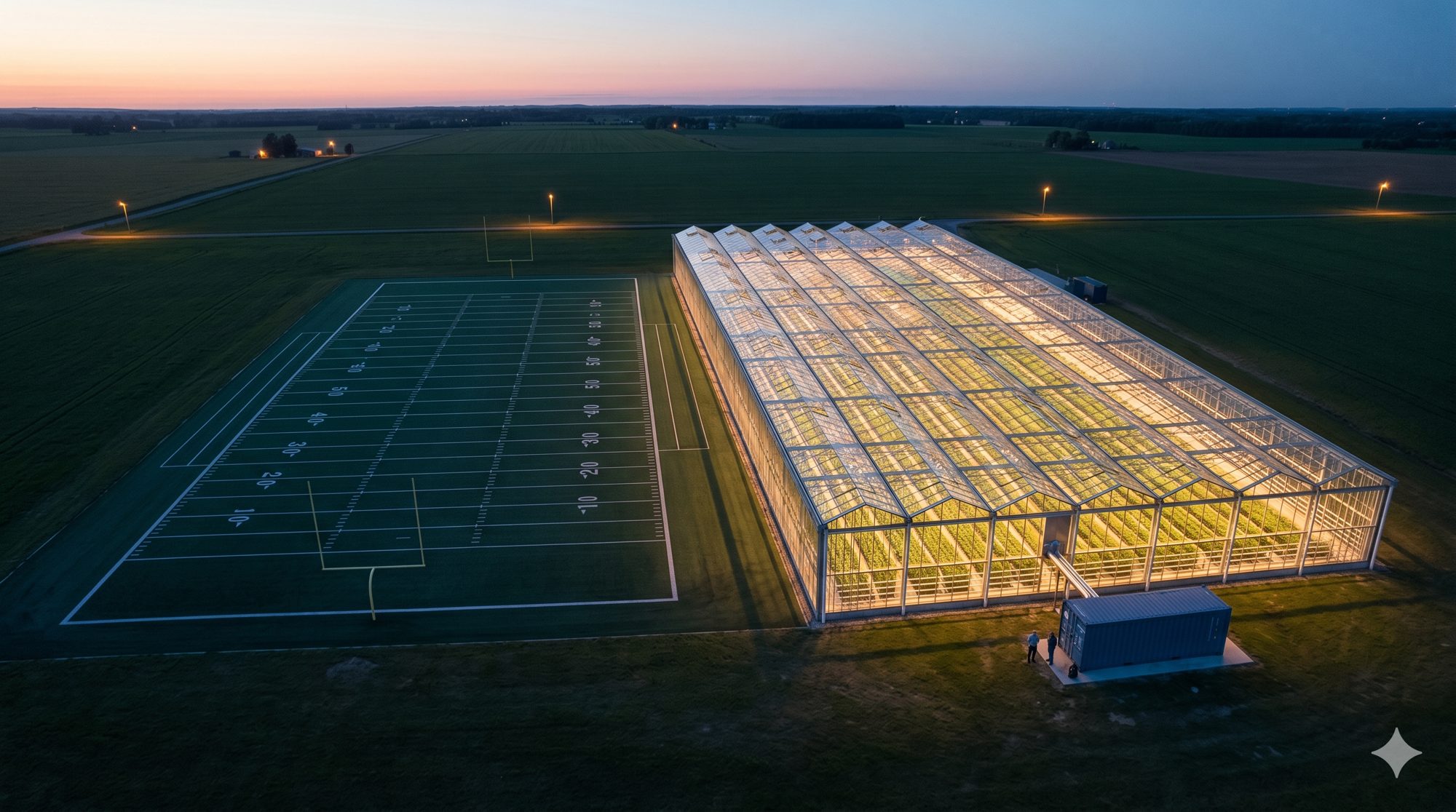
19 / The LinkPart Three
Photo
Heat recovery loop to district heating [a__15_]

Only the hot water
crosses over.

  • The community work connects to the data center by one thing: the recovered hot water that leaves the plant.
  • Everything past this point is its own commitment, co-designed with the neighborhood.
20 / The PrinciplePart Three

Repair and reciprocity,
not charity.

  • The community program is binding and co-designed with the neighborhood's own organizations.
  • It is separate from the data center design and is not a condition the build depends on.
21 / The ThemesPart Three

Programs built on the heat.

Food

The greenhouse

Controlled-environment growing on recovered heat, anchoring food access and training.

Make

The craft brewery

A working brewery on hot water, a visible civic draw and a skills program.

Use

The laundry

A neighborhood laundry on recovered heat, everyday utility for residents.

Gather

The public center

Community and office space, open to the neighborhood.

Learn

The education centre

An interpretive floor with live energy data, built for school groups.

22 / The GreenhousePart Three

Heat becomes food.

Recovered heat runs a controlled environment greenhouse at real scale. Shown here against a football field for size, and as the growing array the warm water can support.

Greenhouse beside a football field
Greenhouse beside a football field, for scale
Data center and greenhouse array
The data center and the growing array it heats
23 / Grown and GatheredPart Three

Heat you can stand in.

The recovered warm loop runs a public conservatory through the cold months and feeds a community growing program on the forecourt.

Photo
Public conservatory [a__1_]
The public conservatory, heated through winter
Photo
Community growing program [a__14_]
The community growing program on the forecourt
24 / The Education CentrePart Three

A place to learn
how it works.

  • An interpretive floor that makes the heat legible: live boards for heat delivered and CO₂ avoided, a working heat-exchanger model, and a thermal camera.
  • Built for school groups, tied to the workforce pipeline and the schools in the sequence below.
Photo
Education centre interior [a__11_]
25 / A Civic AssetPart Three
Photo
Public forecourt, evening event [a__7_]

What the space
gives back.

  • A community floor and offices, a craft brewery, a greenhouse, and a public forecourt.
  • Open to the neighborhood, framed as programming rather than as part of the data center design.
26 / The PartnersPart Three

Co-designed with Grays Ferry.

  • The neighborhood's own organizations lead the design: the Grays Ferry Coalition, Young Chances, the Universal schools, and others.
  • We earn legitimacy first, then fund the trusted doers, on multi-year terms.

[Named partners confirmed once engaged and with consent.]

27 / The AgreementPart Three

Binding, tracked, enforceable.

  • Binding articles with measurable targets and timelines.
  • A public compliance dashboard, and clawbacks tied to missed targets.
  • Resident seats on the governance body.
Mock
CBA compliance dashboard
28 / The SequencePart Three

How we earn it.

Step 01
Earn legitimacy
Listen first, with the coalition and the council office
Step 02
Fund the doers
Multi-year support to trusted grassroots anchors
Step 03
Workforce pipeline
A neighborhood trades feeder with real hiring
Step 04
Anchor the schools
STEM and career pathways through the schools
26 / The AskClose

One next step for each of you.

City and community

Review the draft agreement and co-design the benefits with us.

Partners

Request the technical pack and align on integration.

Investors

Request the financial pack and discuss terms.

Become a partner.
MicroLink Data CentersCape Town · Chicago · New York